Ultrasonic / Electromagnetic Wave
ComWAVETM
Ultrasonic Simulation Software
Samples
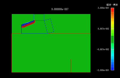
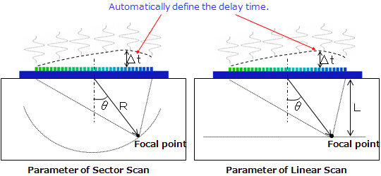
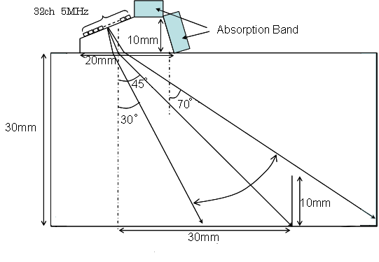
An analysis of B-scope pattern in the case of phased-array prove
Templates for various type of probe are provoded.
Vertical probes, angled probes, Phased array probes, etc. Especially, in the phased array modeling, automatic delay time setting is available.
Modeling
Results
 |
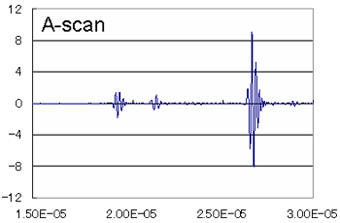 |
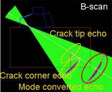
The mode converted echo is useful to estimate the crack depth measurement. However the echo paths are hard to understand only using A and B-scan displays. ComWAVE can show the echo path directly by visualization of ultrasonic propagations.
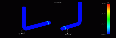
An analysis of Guided Wave in steel pipe
Modeling
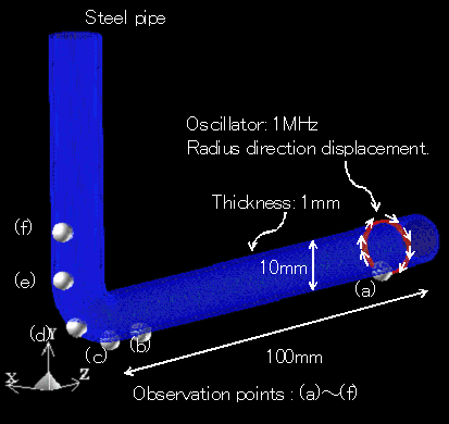
Results
Animation for displacement distribution of ultrasonic propagation.
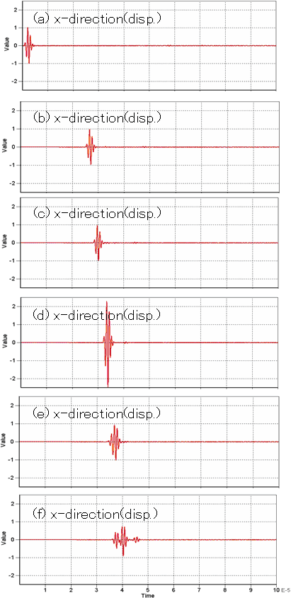
Displacement waveform for observation points.
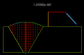
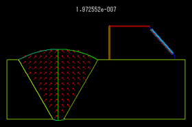
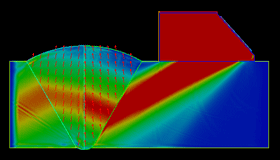
Propagation of transvers wave in Austenite steal weldment
Comparing the propagation paths for different crystal axes in austenite stainless steel weldment.
 |
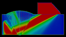 |
Though the weldment shapes are same, the ultrasonic propagation paths are greatly affected by material anisotropy in the weldment. In UT method, the accurate recognition of the ultrasonic propagation path is important to analyze the echo from the defects.
Ultrasonic wave excitation into sylindorial rod
Comparing the propagation paths in cylinder stick for photo-elasticity testing and simulation.
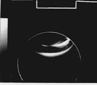 (a) Photo-elasticity testing (a) Photo-elasticity testing |
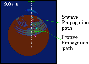 (b) Simulation results (b) Simulation results |
The visualization by simulation is very useful for preventing misunderstanding on the propagation paths in intricate structures.

